A PID is used to operate the process system since it shows the piping of the process flow. Click Add and then type a name for the shape data set.

P Id Flow System Example P Id Diagram Piping And Instrumentation Diagram Example
Choose whether to create a new shape data set a set based on the currently selected shape or a set based on an existing shape data set and then click OK.

. A PID drawing serves as a guide for start-up and operational data. Ad Templates Tools Symbols For PID HVAC Engineering Diagrams. A piping and instrumentation diagram PID is a graphic representation of a process system that includes the piping vessels control valves instrumentation and other process components and equipment in the system.
Learn How to Read PID from the expert. The P ID includes every mechanical aspect of the plant except stream flows pipe routing pipe lengths pipe fittings supports structure foundations. A PID shows all piping including the physical sequence of branches reducers valves equipment instrumentation and control interlocks.
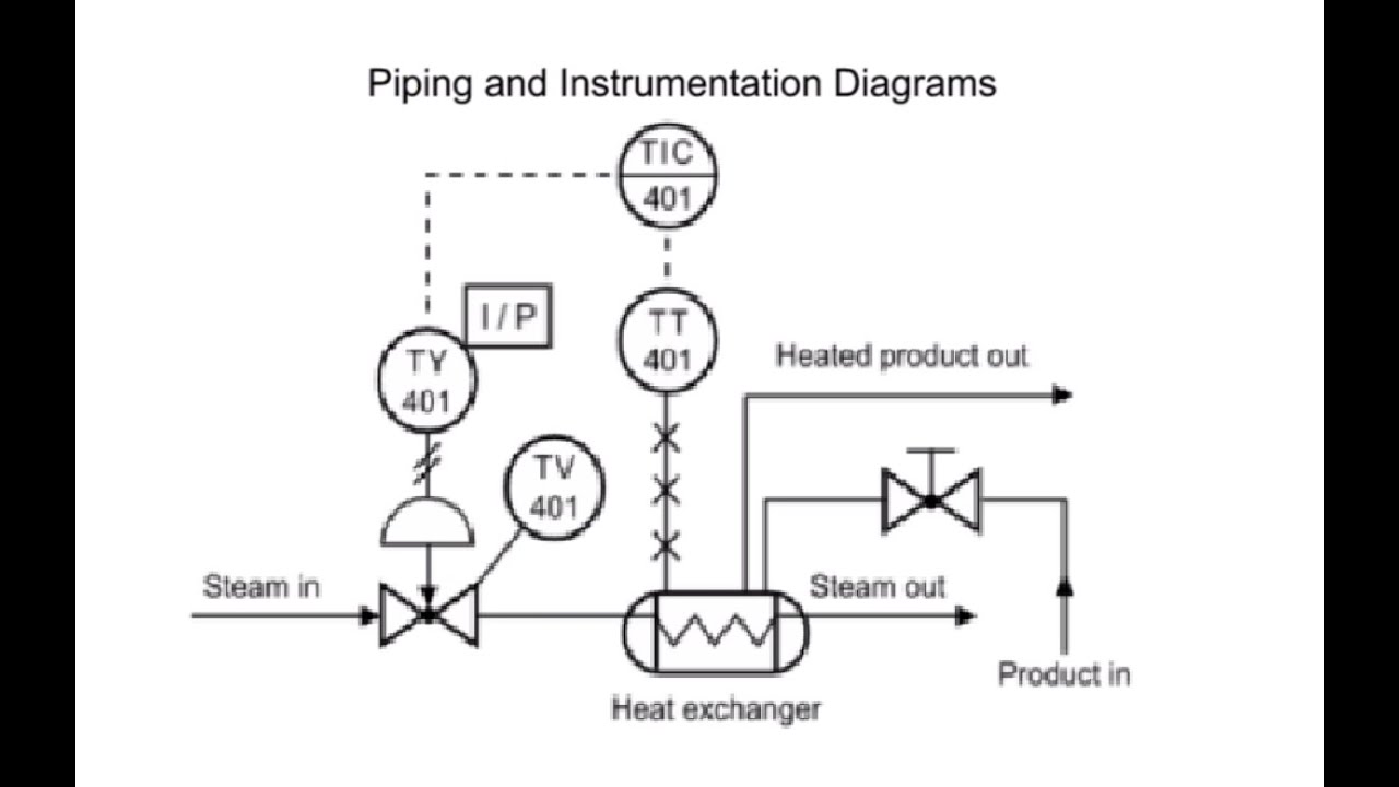
Creating a PID requires an in-depth understanding of the engineering design and the required symbols. All the instruments in a PID are marked by a circle with an assigned tag number and line inside it. The tag number helps in identifying the device whereas the line is the location indicator.
Without a doubt Visual Paradigm Online is the best PID software to create schematics for the process industry. The PID drawings help them to track the interconnection between the. Just select the symbol you need add them on the canvas and connect them to complete your draft in minutes.
The PID is the primary schematic drawing used for laying out a process control systems installation. Our PID designer provides abundant industry-standard engineering symbols which allows you to make an accurate visual representation of the process flow in a plant. It is also important to know how to read its symbols and shapes in the drawing.
Navigate to New Industrial Engineering Step 3. The preset styling options enable you to change the style of all. Key Points to remember about the P ID drawing symbols.
There are few ISO and British standards available that provide symbols and best practices to draw PFD and PID such as ISA S51 BS 5070 and ISO 10628. A Process and Instrumentation Diagram P ID shows the process flow and interconnection of process equipment which is used control a process. PID and PFD Symbols.
For easier understanding the PID is broken into. Log in to your Google Account Google Accounts are free and copy File Make a copy this online PID drawing template to start making your own drawings. A set of standardized PID symbols is used by process engineers to draft such diagrams.
It is the basic training document to explain the process details to operation guys field engineers and maintenance professionals. PID is the acronym for Piping and instrumentation diagram ie. PID symbols are a standard set of symbols used to represent components in a system.
Right-click on Shape Data Window and select Shape Data Sets. P ID drawings have a set of standard symbols used to represent the components in the diagrams. With Visual Paradigm Online you dont need to start each PID from scratch because a rich set of piping.
Typically the core engineering team will define a symbol library to be used on the desired project. FREE online PID diagram drawing template - enabled for the FREE online Google Docs. On the Data tab click Shape Data Window.
Every symbol contains letters and a number. Like a city map the drawing is. Select one PID template to edit on it or click the sign to start from scratch.
A PID provides information to begin planning. But there are criteria that can make PID more efficient. PID is a detailed diagram in the process industry which shows the piping and process equipment toget.
Typically the engineering team will define a symbol library to be used on the project. A Guide to Understanding PID Drawings Learning Instrumentation And Control Engineering We Provide Tools and Basic Information for Learning Process Instrumentation and Control Engineering. PID symbols exist for all major components and lines such as.
The grid can consist of letters numbers or both that run horizontally and vertically around the drawing as illustrated on Figure 2. Superordinate to the PID is the process flow diagram PFD which indicates the more general flow of plant processes and the relationship between major equipment of a plant facility. It uses symbols to represent process equipment such as sensors and controllers.
What to look for in PID diagram software There are lots of software tools that enable diagramming. The symbol used to draw a PID can vary from different industries to projects and clients. P.
EdrawMax provides all kinds of symbols required in PIDs. PID symbols are a graphical representation of physical equipment that installed on the field. The first letter represents the parameter like temperature and the second letter.
To help locate a specific point on a referenced print most drawings especially Piping and Instrument Drawings PID and electrical schematic drawings have a grid system. Subscribe -httpsgoogl9OktFA You will learn how to read PID and PEFS with the help of the actual plant drawingW. A piping and instrumentation diagram PID is a detailed diagram in the process industry which shows the piping and process equipment together with the instrumentation and control devices.
ISA standards adherence ease of use ability to integrate into other productivity tools and most importantly in many cases the power to collaborate with other team members and departments. And you can share your diagram with others via social media and. The PID diagram software comes with a rich set of high-quality PID symbols for you to create different kinds of PID diagrams.
PID drawing is a schematic representation of instrumentations control systems and pipelines used in any process development plant. Pumps and Turbine PID Symbols. As such the PID is.
The symbol used to draw a PID can vary by industry project and client. A PID is known as piping and instrumentation diagram. Select copy and paste the components you want to use.
At first this PID looks complicated but on closer examination it is actually a simple PID. You can export the file to Graphics PDF editable MS Office file SVG and Visio vsdx file. A very detailed diagram showing the processes happening within a plant the involved equipment and their interconnections.
Make your own PID diagrams with this FREE online drawing tool. A piping and instrumentation diagram PID is a drawing in the process industry. A Definition of PID.

Pump With Tank Pid En Piping And Instrumentation Diagram Wikipedia Piping And Instrumentation Diagram Diagram Engineering Education

P Id Guidelines For Centrifugal Compressor Systems Centrifugal Compressor Compressor P Id Diagram

Piping And Instrumentation Diagram P Id Piping And Instrumentation Diagram P Id Diagram Chemical Engineering

Draw P Id Diagrams Online In The Browser With Google Docs P Id Diagram Diagram Online Drawing

What Is Piping And Instrumentation Diagram P Id Piping And Instrumentation Diagram Mechanical Engineering Design Diagram

A Process Flow Diagram Shows The Relationships Between The Major Equipment S Columns Ves Process Flow Diagram Process Flow Piping And Instrumentation Diagram

Difference Between A Pfd And P Id The Process Piping Piping And Instrumentation Diagram Process Flow Diagram P Id Diagram

P Id Flow System Example P Id Diagram Piping And Instrumentation Diagram Example

Process And Instrumentation Drawing Example Piping And Instrumentation Diagram P Id Diagram Mind Mapping Tools
How To Read Piping And Instrumentation Diagram P Id Piping And Instrumentation Diagram P Id Diagram Diagram

What Is A P Id Diagram In Laymen S Term Realpars P Id Diagram Diagram Symbols

Flowchart Maker How To Read Piping And Instrumentation Diagram Piping And Instrumentation Diagram Diagram P Id Diagram
What Is A P Id Diagram In Laymen S Term Realpars P Id Diagram Diagram Piping And Instrumentation Diagram

Process Diagram Symbols Field Instrumentation Industrial Automation Plc Programming Ingenieria De Procesos Proyectos De Ingenieria Ingenieria De Control

Plc Control System Control Systems Engineering Piping And Instrumentation Diagram Control Engineering

A Piping And Instrumentation Diagram P Id Is A Schematic Illustration Of Functional Relati Piping And Instrumentation Diagram P Id Diagram Mind Mapping Tools

Water Boiling Process Pid Free Water Boiling Process Pid Templates In 2022 Piping And Instrumentation Diagram Mind Mapping Tools P Id Diagram

Example P Id Piping And Instrumentation Diagram P Id Diagram Mechanical Engineering Design

Piping And Instrumentation Diagram P Id Software Piping And Instrumentation Diagram Id Software P Id Diagram